Project
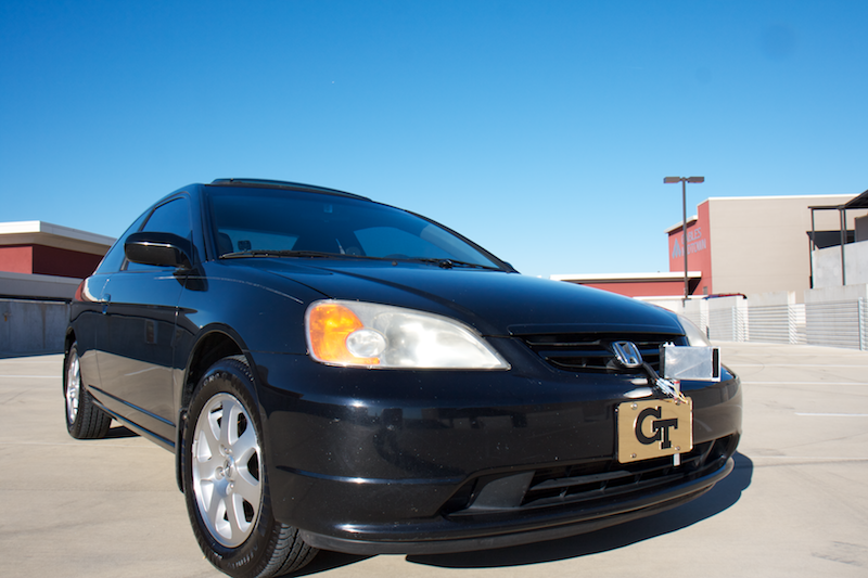
In the Fall of 2011, Team Road Rage, a group of Georgia Tech seniors, initiated a project to design and develop a vehicle collision avoidance system that fulfilled the course requirements for Georgia Tech’s ECE 4007: Senior Design. The team ultimately built an innovative system that successfully warned drivers when their time headway, relative to a lead vehicle, fell below a predetermined safety threshold. The benchmark safety threshold was dynamically determined based on environmental conditions and calculated reaction time of the driver.
Motivation
According to the National Safety Council, 26.5 percent of all vehicular accidents are rear-end collisions. Although these rear-end collisions are responsible for only 4.3 percent of traffic-related fatalities, they are responsible for one-third of all collision-caused traffic delays, resulting in 157 million vehicle-hours of traffic delay annually. According to police reports, 64 percent of these rear-end collisions are the result of driver inattention; 14 percent are a result of following too closely; 3 percent are due to poor visibility; and 2 percent are caused by the driver’s poor judgment.
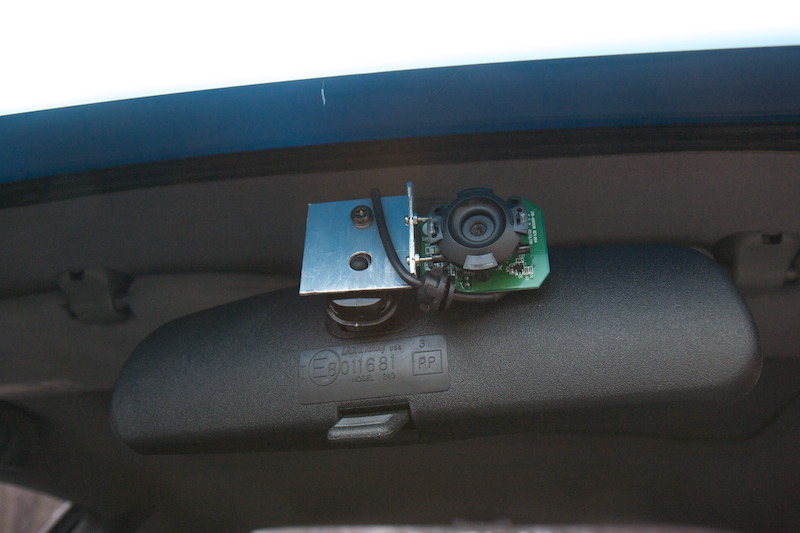
At the inception of Team Road Rage’s project, commercially-available collision avoidance systems offered some limited features, such as lane departure and driver inattention warnings. However, they were incapable of taking into consideration the driver’s unique driving behavior and real-time road surface conditions. The Team Road Rage system integrated the aforementioned real-time data and could easily be incorporated into other driver assistance packages. The Team Road Rage system differentiated itself from other more expensive collision avoidance systems by utilizing a one-dimensional laser rangefinder and a low-resolution camera instead of more costly sensors, such as a long-range radar or stereo camera.
Components
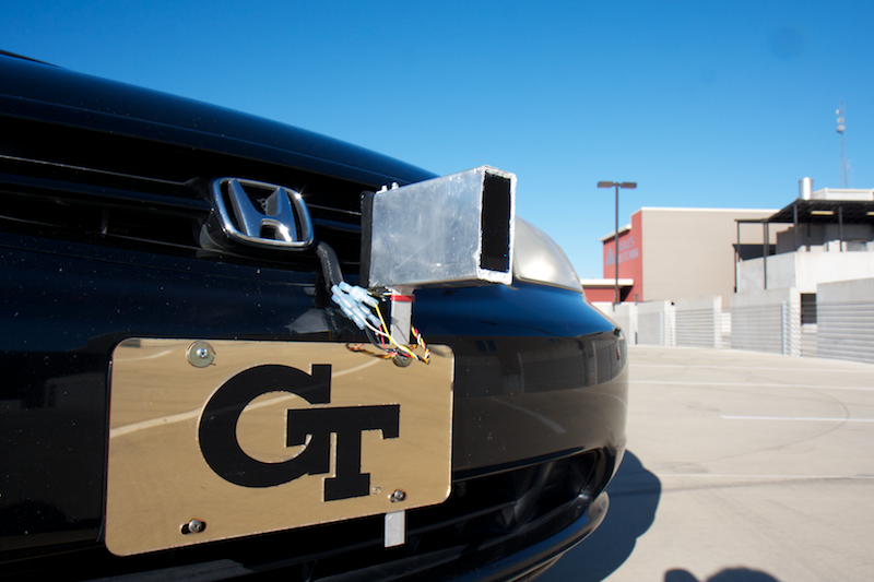
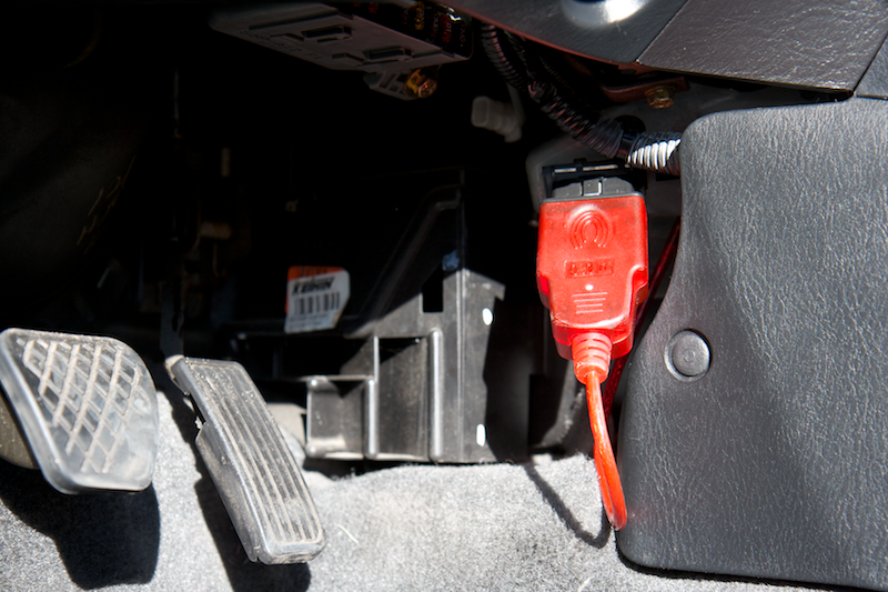
The Team Road Rage system utilizes five primary data input sources: a laser rangefinder, which measures the distance from the ego vehicle to a lead vehicle; a rain sensor, which detects precipitation on the windshield; an OBD-II scanner, which measures the instantaneous velocity of the vehicle; a temperature sensor, which detects whether icy conditions may exist; and a USB camera, which detects and tracks lead vehicles. The primary driver interface is an Android mobile phone, which displays the instantaneous time headway to the lead vehicle and issues auditory alerts through the vehicle’s speaker system.
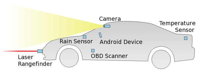
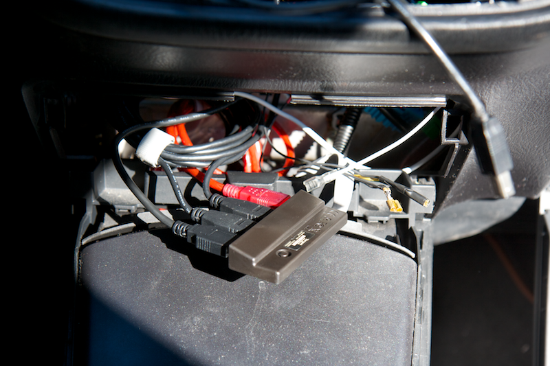
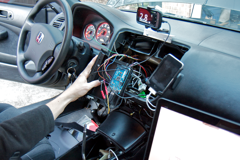
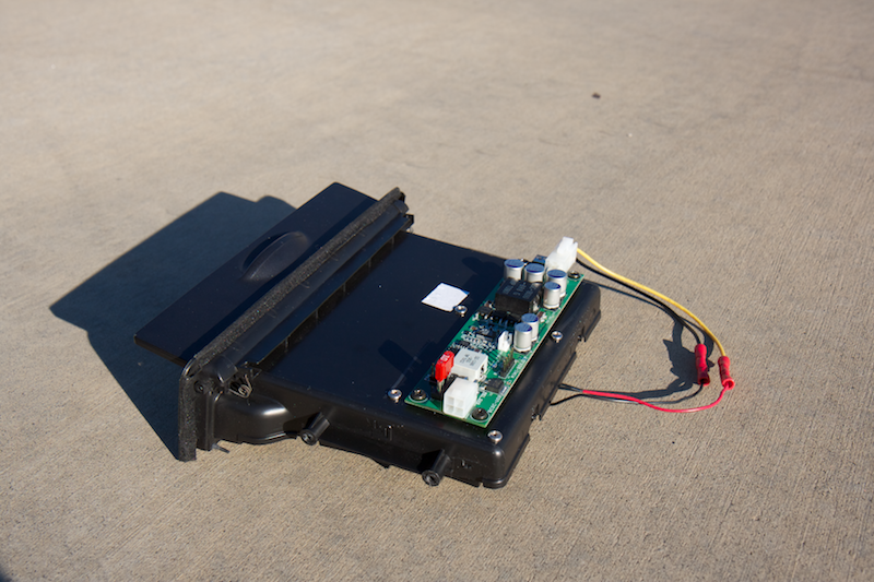
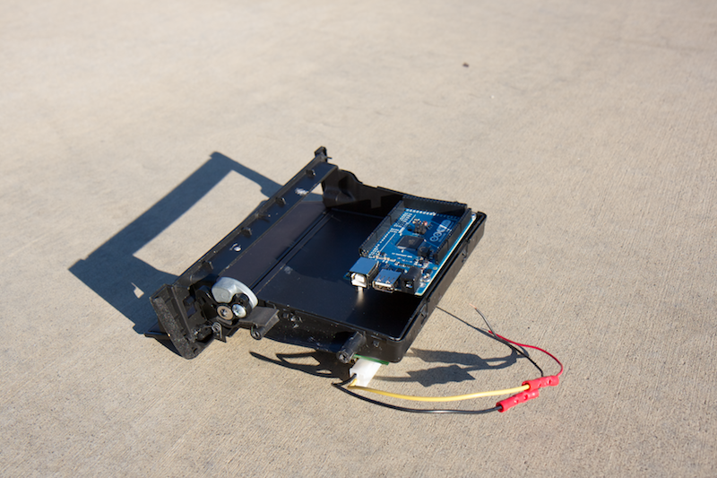
The sensors are connected to a central controller (laptop computer), either directly over USB, or indirectly through an Arduino ADK microcontroller. The Arduino also serves as a mechanism for forwarding serial communication to the Android mobile phone.
Software
The controlling laptop computer runs a Linux operating system, customized to include only essential features and services. The function software is written in C++ and utilizes several supporting libraries, including Qt, OpenCV, libFTDI and CUDA. The controlling application makes use of multiple threads, allowing each asynchronous component of the system to run independently, passing data to the controlling thread only when necessary. The system architecture has a modular design, employing multiple levels of functional abstraction to support the various software components and device interfaces. The following diagram provides a basic overview of the major software components of the system:

The blue components identify system inputs, while the red components designate system outputs. Objects marked with an asterisk represent those whose instances live in threads of their own. As new information becomes available, data is passed across thread boundaries using Qt’s “signals and slots” mechanism. Several classes were created specifically to safeguard data in the multi-threaded environment. For example, the purpose of the “ArduinoDevice” is to ensure that only a single object communicates with the Arduino at any given instant. Without this safeguard, objects on different threads could try to simultaneously send data to the Arduino, resulting in a communications failure.
Asynchronous Sensor Fusion
In order for the system to function successfully in real-time, each sensor must continually provide updates with minimal latency. To accommodate continuous sensor updates, the software design allows each sensor to update asynchronously, registering each sensor’s updates as they become available. Asynchronous updates aren't an issue for sensors whose readings are used independent of other sensors’ readings (e.g., temperature sensor and rain sensor). However, integrating readings from the speed sensor and the distance sensor presents a design challenge, because the two sensors provide updates at different rates. To further complicate the problem, the laser rangefinder utilized for the prototype system occasionally reports distance values that are invalid. Although a number of factors could contribute to the invalid data, the two most common causes seem to be poor reflectivity of the lead vehicle (common when following black vehicles) and misalignment (typical on curved road segments). Since the system must maintain functionality until the next valid reading can be obtained, a Kalman filter is utilized to predict future system states and compensate for noisy sensor inputs. Unfortunately, a generic Kalman filter requires simultaneous sensor readings in order to interpret data and make system corrections, as shown below.
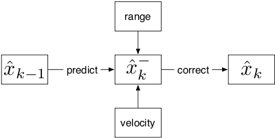
To solve the design challenge, the function was re-engineered to have the internal parameters of the Kalman filter dynamically modified as measurements become available. This process is shown below.
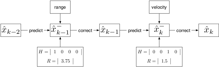
This improvement enables the asynchronous fused Kalman filter to function without placing restrictions on the sensor rates and still provide estimates when readings are noisy or invalid.
Safe Time Headway Calculation
One unique aspect of the Team Road Rage system is that it’s dynamic, incorporating data on real-time environmental conditions (wet or icy roads) and the driver’s reaction time. This feature makes the system extremely versatile and able to accommodate a wide range of road surfaces and driver skill levels.

A reverse-engineered, off-the-shelf rain sensor mounts to the inside of the windshield and detects precipitation. The rain sensor uses infrared light to detect changes in the glass windshield’s refractive index, which is caused by the presence of water on the opposite surface. When precipitation is detected multiple times within a given period, the safe time headway is elevated for the next half-hour. A temperature sensor, mounted behind the front-left wheel well (away from the heat of engine components) perceives potentially icy conditions. If the temperature drops below five degrees Celsius, the function assumes ice may be present on the road surface, and the safe time headway is increased for the remainder of the trip.
An innovative aspect of the system is a unique method of calculating the driver’s reaction time. This is accomplished by monitoring the calculated speed of the lead vehicle and looking for decelerations greater in magnitude than -6 m/s². Whenever such decelerations are detected, if the time headway is below a pre-specified threshold, a timer is started that runs until a similar response is detected from the driver of the ego vehicle. If the driver of the ego vehicle brakes within three seconds, the reaction time is averaged into the previously recorded reaction time. Over time, reaction times calculated using these “braking events” allow the system to adapt to the individual driver.
Alerting the Driver
After thoroughly reviewing many studies concerning methods for alerting drivers to dangerous conditions, the team settled on a hybrid alert system that utilizes both visual and audible warnings. The visual warning system provides the driver with a real-time graphical representation of the relative “safeness” of the current time headway to the lead vehicle, giveing the driver the opportunity to react accordingly. If the driver permits the time headway to remain below the minimum safe time headway, an abstract tone is sounded through the vehicle’s speaker system.
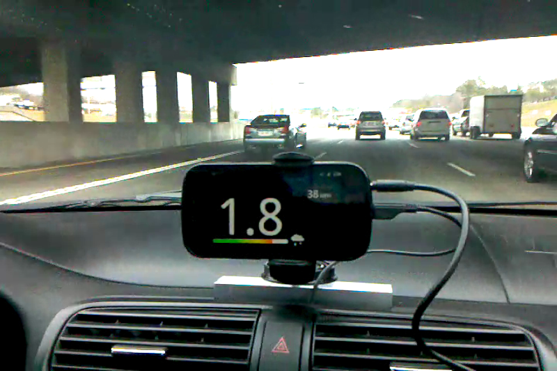
In a production system, these alert mechanisms (pictured above) would ideally be incorporated into the in-dash HMI. In the prototype system, an Android mobile phone was used for the real-time visual display and the mobile phone’s audio output was connected to the auxiliary input of the vehicle’s stereo system. The phone, strategically mounted in the center of the dash, is clearly visible to the driver, but does not occlude the view of the road ahead. The phone’s display includes the instantaneous time headway, the calculated velocity of the lead vehicle and a custom indicator representing the relative “safeness” of the time headway.
Video
Photos
Click to view images in more detail.